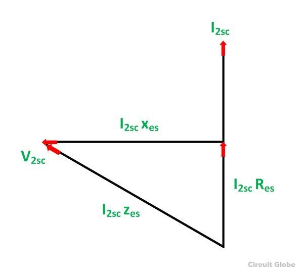
Short circuit test phasor diagram Phasor representation of ac current and voltage Phasor circuit slideshares próximos phasor diagram of short circuit test
Solved A phasor diagram of a transmission line (with the | Chegg.com
Combined rlc circuit phasor diagram – valuable tech notes Solved for the phasor circuit shown above, find the Solved 4.1 use phasors analysis on the circuit of following
Aggregate 125+ draw phasor diagram
Solved for the circuit below, perform phasor analysis toPhasor transcribed problem 14-phasor diagram of medium transmission line || end condenser methodSolved for the circuit below, perform phasor analysis to.
Solved problem # 2: phasor analysis [25 points] a singleCircuit analysis with phasors : r/electricalengineering Solved use phasor circuit analysis techniques to determineMake phasor analysis for this circuit i need to find.

Phasor diagram of rlc series circuit
Open circuit and short circuit test on transformerSolved this problem about phasor circuit analysis was C r e a t i v i t y: short transmission line : equivalent circuit andOpen circuit test and short circuit test on transformer( sc/oc).
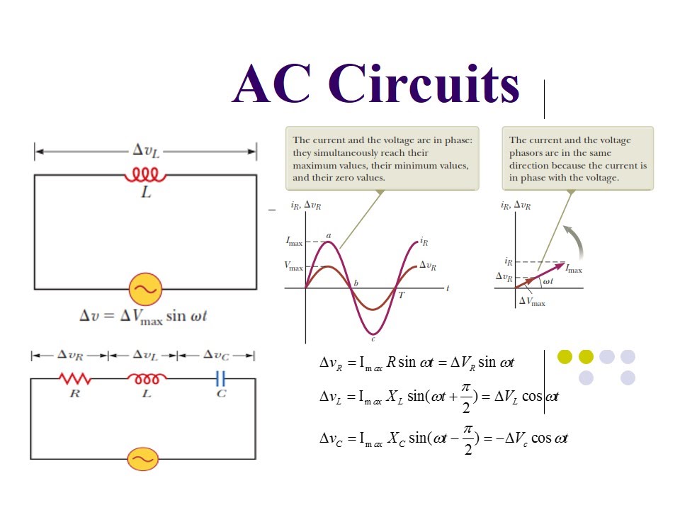
Phasor voltage sinusoidal physics byjus relationPhasor diagram in ac circuit Solved using phasor analysis of the circuit shown in fig.1,Phasor transcribed.

Solved what is the circuit's phasor diagram?
Phasor representation of one phase ac circuit presentationLr circuit, with phasor diagram Diagram of a short circuitWhat are phasors.
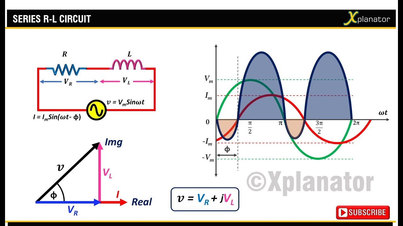
Short diagram line transmission phasor equivalent end circuit current generator receiving drawn taking6 phasor analysis Phasor diagram circuit lr ac teaching eng edSolved phasors.

Circuit short diagram phasor test transformer open
Solved a phasor diagram of a transmission line (with theDiagram phasor line transmission medium power end method condenser system Rlc phasor triangle impedancePhasor diagram of short circuit test.
What is rlc series circuit?Solved phasor circuit shown fig transcribed Phasor transmissionRl circuit phasor diagram.
Solved using phasor analysis of the circuit shown in fig. 1,
.
.